Tangible (Physical Prototyping)
As part of a course in my graduate design program, I designed and built an engineering prototype of a product proposed by a friend. This included concept development, hardware component selection and build, development of a simple UI, and programming an arduino microcontroller.
Problem Statement
My inspiration for this project came from a product idea expressed by a friend:
After staying in one-too-many AirBNBs with horrible blue lighting, I'd love to have a little [...] nice-color-temperature LED paper lantern of sorts. [...] Probably wouldn't be too difficult on the margin to make this into one of those increasingly-bright-light-alarm clocks.
I sought to explore this idea by creating prototype hardware from easily sourcable parts.
Research & Analysis
I conducted competitive market analysis by looking into similar devices already on the market. I also looked into components I could use for prototyping. Using an arduino microcontroller was a requirement of the course, so this served as my starting place for hardware. I also spoke and brainstormed with my friend. Most of his thoughts and ideas related to the physical form that a final product might take.
Ideation & Concept Development
Most of the concept development revolved around the hardware of the device. For inspiration, I looked into easily obtainable sensors, input devices, and other hardware that would work with the arduino microcontroller platform. To help limit scope and speed prototype development, I focused especially on modules that would be "plug and play" with the arduino I2C interface.
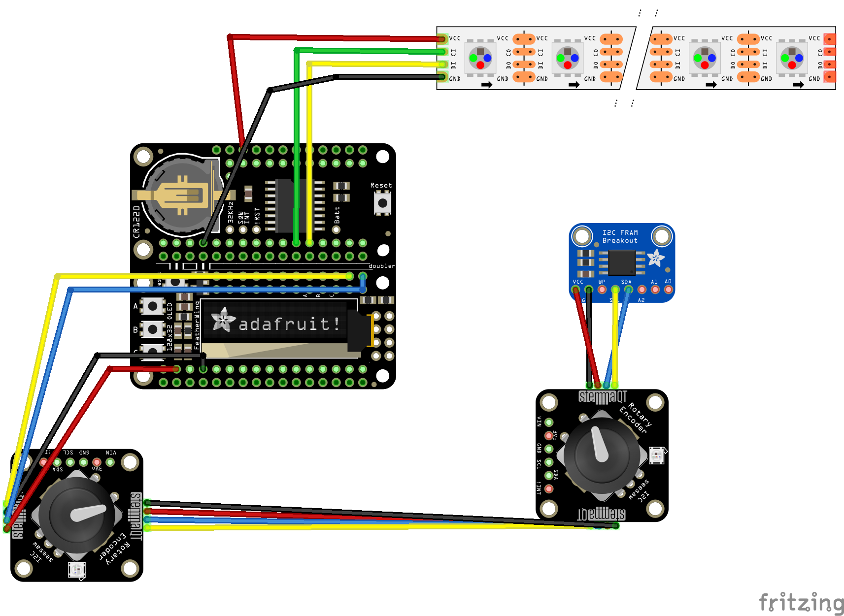
In addition to the arduino microcontroller, I identified a few modules that would provide critical capabilities for the product features I wanted:
Baseline / Required by Assignment
- Adafruit arduino microcontroller
- OLED screen
Supporting Capabilities for Product Features
- RTC clock module with battery backup, enabling alarm clock functionality and the device to keep time when not connected to power.
- LEDs in both a "warm" and "cool" color temperature, enabling user to select color temperature and potentially automatic color temperature shifting throughout day.
- Non Volatile Memory (NVRAM), to store settings when device is not connected to power.
- USB C power (see lessons learned), enabling the device to potentially be powered by laptop or other power brick that user is probably already carrying on travel.
Just for Fun
- Rotary encoder - Nice to use :-)
- White DOTSTAR LEDs - Each dotstar LED actually contains 3, individually addressable LEDs. Using these gave me the ability of much finer control of brightness and color temperature than if I had used another type of LED.
Considered but not Pursued
- LoRA / GPS module - I imagined a feature such as a self-setting clock according to the device's location, and using a LoRA IOT connection to get information like the weather. I decided these were not important features for most end users, although I do hope to explore LoRA radios some day.
Prototyping & Testing
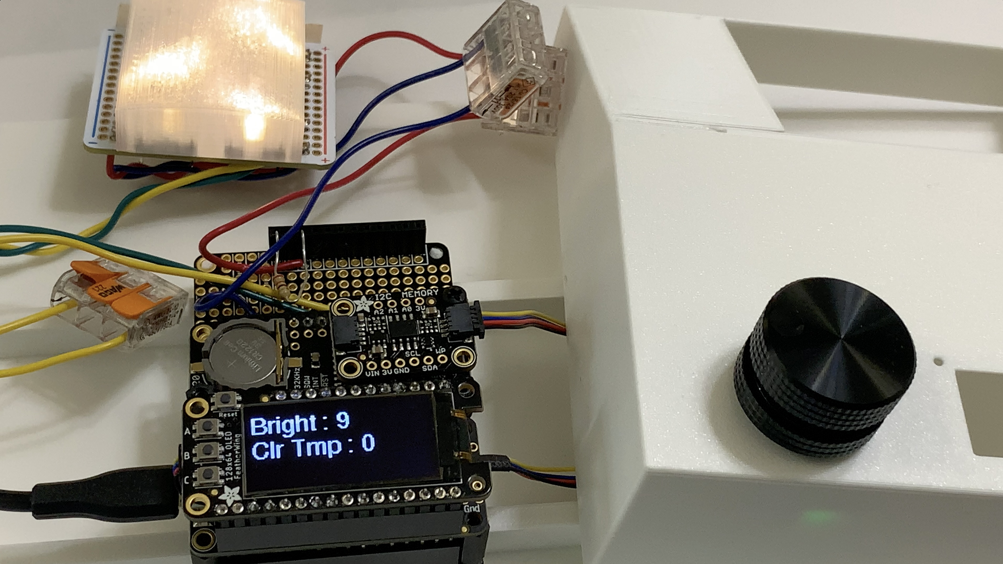
I assembled the device, including designing and 3D printing a diffuser for the LEDs and the assembled circuitry. I also wrote code for a simple UI.
Within the time limits of the course, I was able to implement a simple UX that used two knobs to change the brightness and color of the LEDs, with the OLED screen showing the currently selected brightness level and color temperature.
Implementation & Results
The device was shown at a "project fair" as part of the course. People generally liked the product, and in particular, many people remarked on how nice the encoder knobs were to use. A "physical delight."
If I were continuing with this product, I would look into a much simpler screen (Possibly a segmented LCD, eInk, or something not backlit). More importantly, I would need to make the product much smaller and lighter.
Human centric interactions:
“Any sufficiently advanced technology is indistinguishable from magic.”
- Arthur C. Clarke
Considerable effort was put into creating a product that behaved in an intutive way. Some examples below:
Non-Linear Brightness
Human Centric / Intuitive behavior:
User would expect the brightness to increase in a "smooth" linear way, even though human perception of brightness is logarithmic.
Engineering "default behavior":
Map input values linearly to output valies, which would result in a light that the user perceived as having big jumps in brightness at lower input values, and no perceptable jumps in brightness at higher input values. The user might think the light was broken.
Engineering required for human-centric behavior:
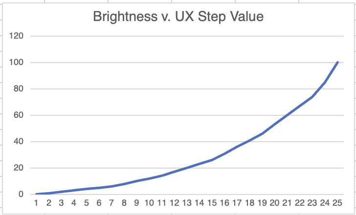
Map linear "input" values to non-linear "output" values. I could have done this completely mathematically. Because my UX had 25 steps of brightness (Indicated as 0 to 24 on the OLED screen), I made a decision to map these manually instead. This way I could "cheat" and add slightly more fineness-of-adjustment to the lower-end of the adjustment range than the high end, taking into context that since this device would be used "bedside."
Note below that the first 50% of the UX-selectable range (0-12) only cooresponds to the first 20% of the LEDs output capability.
//uint32_t pixelwht = strip.Color(100, 100, 100);
int colorTable[] = {0,3,6,9,13,17,21,26,31,36,42,48,54,61,68,75,83,92,103,116,132,153,180,214,255};
int brightTable[] = {0,1,2,3,4,5,6,8,10,12,14,17,20,23,26,31,36,41,46,53,60,67,74,85,100};
Virtual Stops and Number of Steps
Human Centric / Intuitive behavior:
The knobs should behave similarly to an analog potentiometer. That is, they should have a "minimum" and "maximum" that cannot be exceeded.
On a potentiometer, this is a physical limit - the knob simply cannot be turned past its limit. Although these rotary encoders can turn continuously, the software will need to behave as if there are "stops."
For most light dimmer knobs people encounter, a ~270-360º rotation (and no more than this) controls the entire brightness range of the light. Since these encoders have 24 detents per 360º and I wanted one full turn of the knob to cover the entire brightness range of the light, I split the brightness into 24 increments.
Engineering "default behavior":
The simplest way to implement an encoder is to have it increment and de-increment when turned, and then do something with this value.
A common method would simply step though the values in the output table. The challenge with this is that it can cause erratic behavior such as looping through lookup values, so at the ends of the range, the device jumps from its highest brightness to its dimmest (or vise versa).
Engineering required for human-centric behavior:
Instead, I developed a solution that evaluated the encoder's "to be" position against the minimum and maximum, and remapped anything beyond the range back into the range.
//Calculate the proposed encoder position and store the (limited by min/max)//value into the encoder safe array encoderProposed = encoder_safe[enc] + encoderDelta; if (encoderProposed < encoder_min[enc]) { encoder_safe[enc] = encoder_min[enc]; } else if (encoderProposed > encoder_max[enc]) { encoder_safe[enc] = encoder_max[enc]; } else { encoder_safe[enc] = encoderProposed; } Serial.print(" SafeVal: "); Serial.println(encoder_safe[enc]); refreshStrip = true; }
Click knob when device is off
Human Centric / Intuitive behavior:
Make the light come back on, at its last-set value.
Engineering required:
Store the "last on" value when the device is turned off, so that this value can be restored if the knob is clicked again.
Turn knob when device is off
Human Centric / Intuitive behavior:
Light should come on at dimmest possible setting (mimick analog dimmer knob).
Engineering required:
When the device is turned off by clicking the knob, then set the encoder value "as if" the device was turned off by turning the knob rather than clicking it. Store the prior value in case the knob is clicked again.
//Encoder Pressed functionint encoderPressed(int encPressed){int action;action = encPressed;switch(action) { case 0: Serial.println("Turn on/off"); refreshStrip = true; if (encoder_safe[0] > 0) { brightnessWas = encoder_safe[0]; encoder_safe[0] = 0; //strip.setBrightness(brightTable[encoder_safe[0]]); //strip.show(); } else { encoder_safe[0] = brightnessWas; strip.setBrightness(brightTable[encoder_safe[0]]); strip.show(); } break; case 1: encoder_safe[1] = 24 - encoder_safe[1]; refreshStrip = true; break; default: Serial.println("Err"); break;}
Lessons Learned
Through the process of building and demonstrating this prototype, I found lots of options to go beyond a simple light and create more joy for the user.
I found that it's very difficult to simultaneously do software and hadware design on a solo project. For example, I ended up with hardware components that I could not implement software to make use of within the course timeline. If I performed a similar project in the future, I would build a better iteratative strategy that provisionsed for future capabilities in both the hardware and software that I imagined wanting to implement in a later date.
I also saw firsthand the extent that adding features for a delightful UX often creates additional complexity in the coding. Although not a substitute for user testing and conversations with engineering teams, developing a strong intuition around usability concerns and engineering techniques will help with categorizing features for their desirability (essential / nice to have / less important) and implementation difficulty.
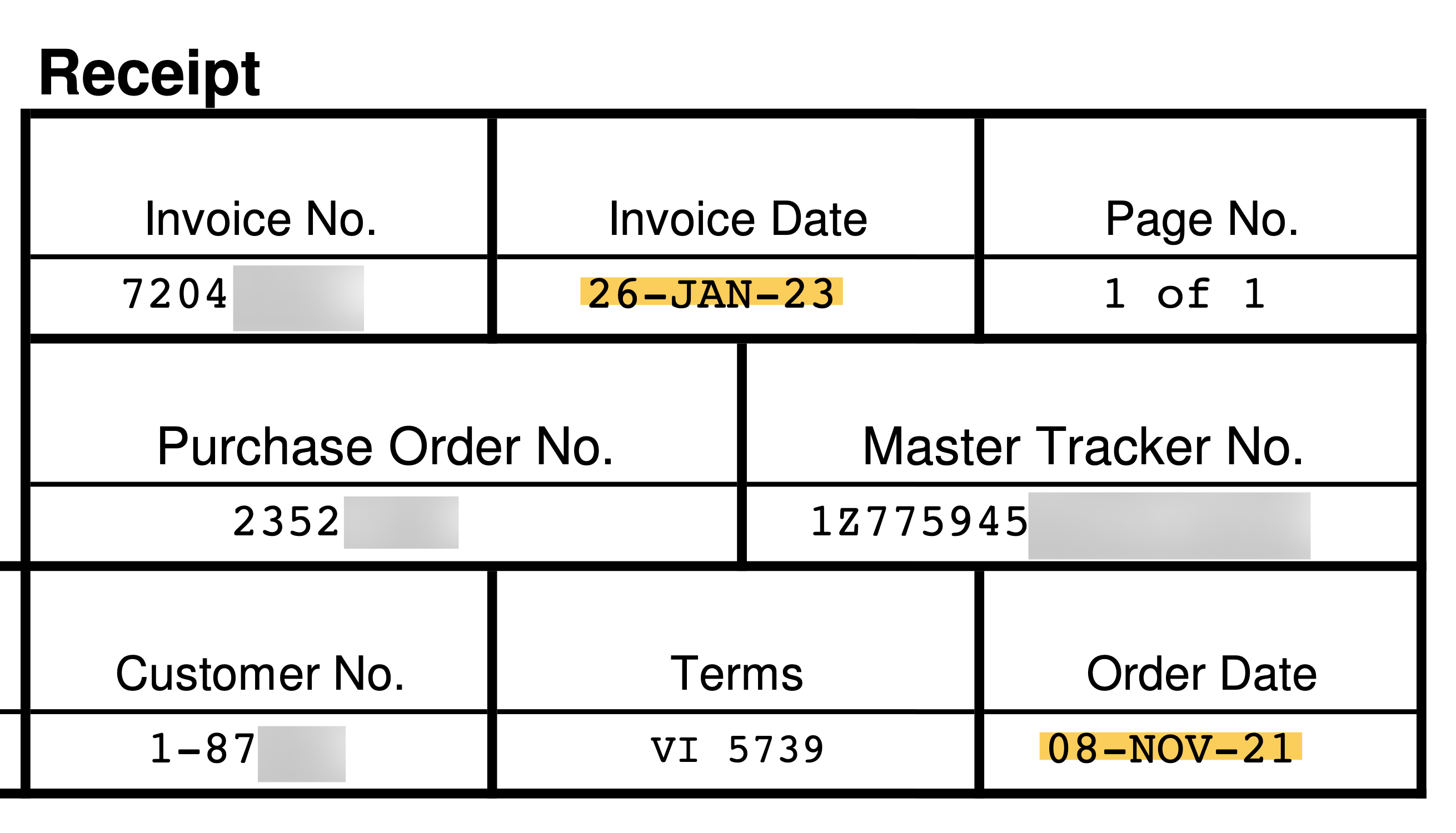
Finally, I experienced supply chain difficulties in this small project! I wanted to implement a USB-C power board that would accept USB-C input to both power the arduino and provide power directly to LEDs, potentially enabling brighter LEDs. I ordered the part in late 2021 and did not receive it for ~15 months.
Conclusion
This project and course presented an exciting opportunity to apply some design thinking while using my engineering talents. I enjoyed the process of creating hardware and writing software to make the hardware work. Moving forward, this project will help me to relentlessly simplify and focus on items of most value to potential audiences / users.